Virtual Modeling
|
Virtual Modelers (VM) is intended to be a temporary, loose affiliation of modelers building the "same" kits and connected by the Internet. These groups will form to tackle similar projects. The results will be displayed on this web site. And, the group will be able to communicate via an email list to discuss topics related to the kit-building effort at hand. Here are the details: The group is designed to allow modelers who are building specific Illinois Traction / Illinois Terminal related projects to share ideas, techniques and the finished models. Every 2-4 months we will select a new project to pursue as a group. Only IT projects will be considered and only messages related to those projects are appropriate. Projects may include rolling stock (freight or passenger), buildings or other IT related items. All scales are welcome to participate! Once the group starts, the modelers will use the email list to share information pertinent to the kits, ask questions, assist others through such means as posting in-progress photos to aid others. The goal is for everyone to complete his or her model within two to four months and submit photos so that the group's efforts may be posted together. If you would like to participate, but cannot photograph your models, we will locate someone who can assist you. Previous skills or experience is not a requirement. Only a commitment and desire to complete the project is necessary. We hope you will join us! Virtual Modeling 1.0
|
|
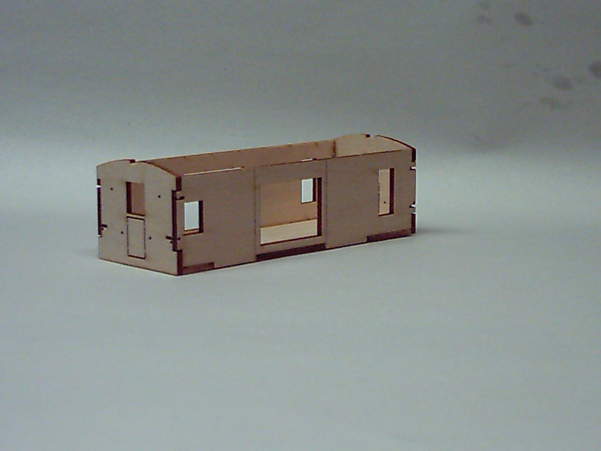
Here's a quick view of the basic box parts prior to assembly. Note that the sides are keyed to the floor. When you assemble the sides to the floor, be certain that the laser cut lines on either side of the bay window opening are facing to the outside of the box! I found that using a single edge razor blade to cut out the individual pieces was easier than using my trusty X-Acto No. 11 knife. After the parts were cut out, I chose one of several "liberated" emery boards to clean the little bit of material left from the laser cutting process to hold the parts to the original sheet. |
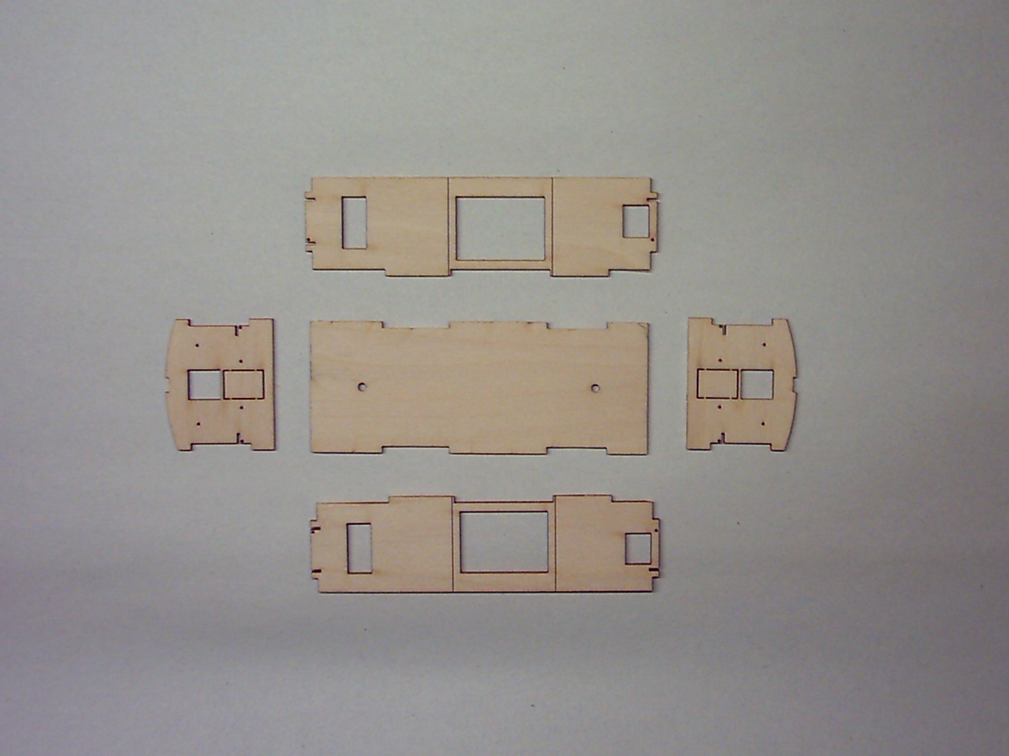 Basic Box Parts |
This view shows the first side (2) and end (4) assembled to the floor (1) with my "Poor Man's Angle Block". Yes, it's really a partially full container of single edge razor blades. While I think I could have assembled the side and end without the "angle block", I felt much more comfortable using it as an aide in assembly. The view to the right and below shows more or less how I used the "angle block' to help maintain a square angle as I applied the recommended Hot Stuff Super 'T' glue. I use a bent pin chucked in a pin vise to apply the glue sparingly. I have learned that less is truly better! |
|
Also, note an idea I picked up from Al Westerfield. He suggests using a small piece of glass for a work surface. This has become a real benefit as the glass and everything on it can be picked and easily moved if it is needed. In addition, I picked up a small 12 quart plastic container with lid to store my project when I'm not working on it. I had a double-strength piece of glass cut so that it fits in the container leaving enough room for my fingers to be able to lift the glass out of the container. I also use an out of the way area of the glass to place two or three drops of Super 'T' glue. I can then dip the bent pin "applicator" into the glue and apply it to the appropriate joint as desired. The glue flows right into the joint without leaving a lot of unnecessary buildup. When the glue puddle hardens from exposure to the air, simply use a single-edge razor blade to scrape the spent glue from the glass and dispose of it. |
 Step 1 showing use of "Angle Block" |
This
view shows the first side (2) and end (4) assembled to the floor (1)
from above. With the way the parts are keyed together, it would
be virtually impossible for them to not fit together well and
squarely. Nevertheless, I felt a bit more comfortable using my
"Poor Man's Angle Block". |
 Step 1 from Above |
This
view shows the first side (2) and end (4) assembled to the floor (1)
from the side. In this view you may notice the slight
discoloration along the joints from the Super 'T' glue. Even
though there is no significant glue buildup, I elected to avoid the
very top of the corner joint as cautioned in the instructions. I
can always return later and finish gluing the top of the joint if it
won't interfere with the fit of the roof assembly. |
 Step 1 from the Side |
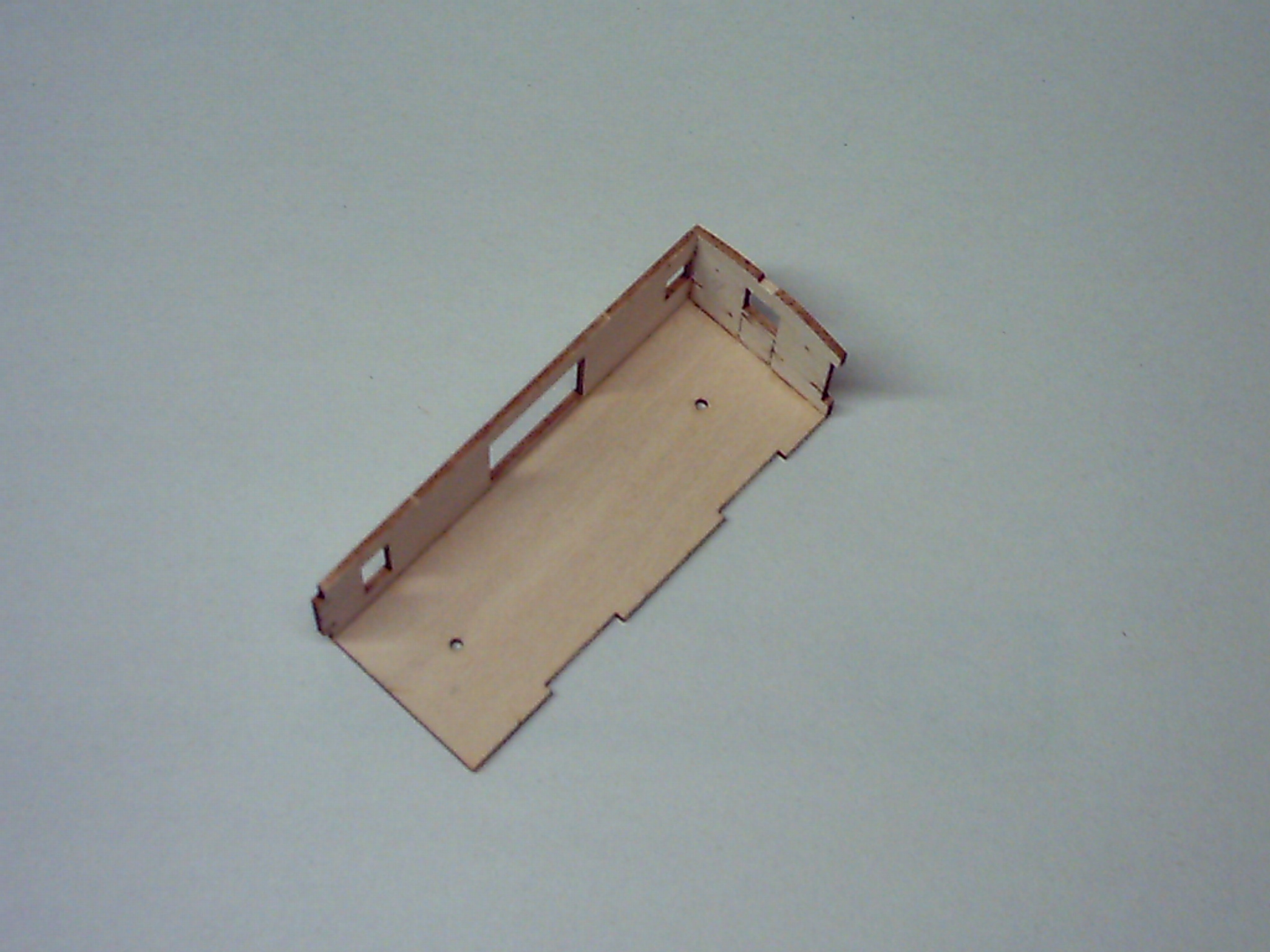
This
view shows the basic box completely assembled now. It also shows
a nice overview of how the joints are all keyed together with varying
sizes of "tabs" and "slots". |
 Step 2 from the Side |
This
view shows the basic box completely assembled from. Again, it
shows a nice overview of how the joints are all keyed together with
varying sizes of "tabs" and "slots". In addition, since the glue
doesn't show any noticeable buildup, I decided to go ahead and glue the
joints at the top of the sides and ends. I just made certain that
I used even less Super 'T' than in other joints. |
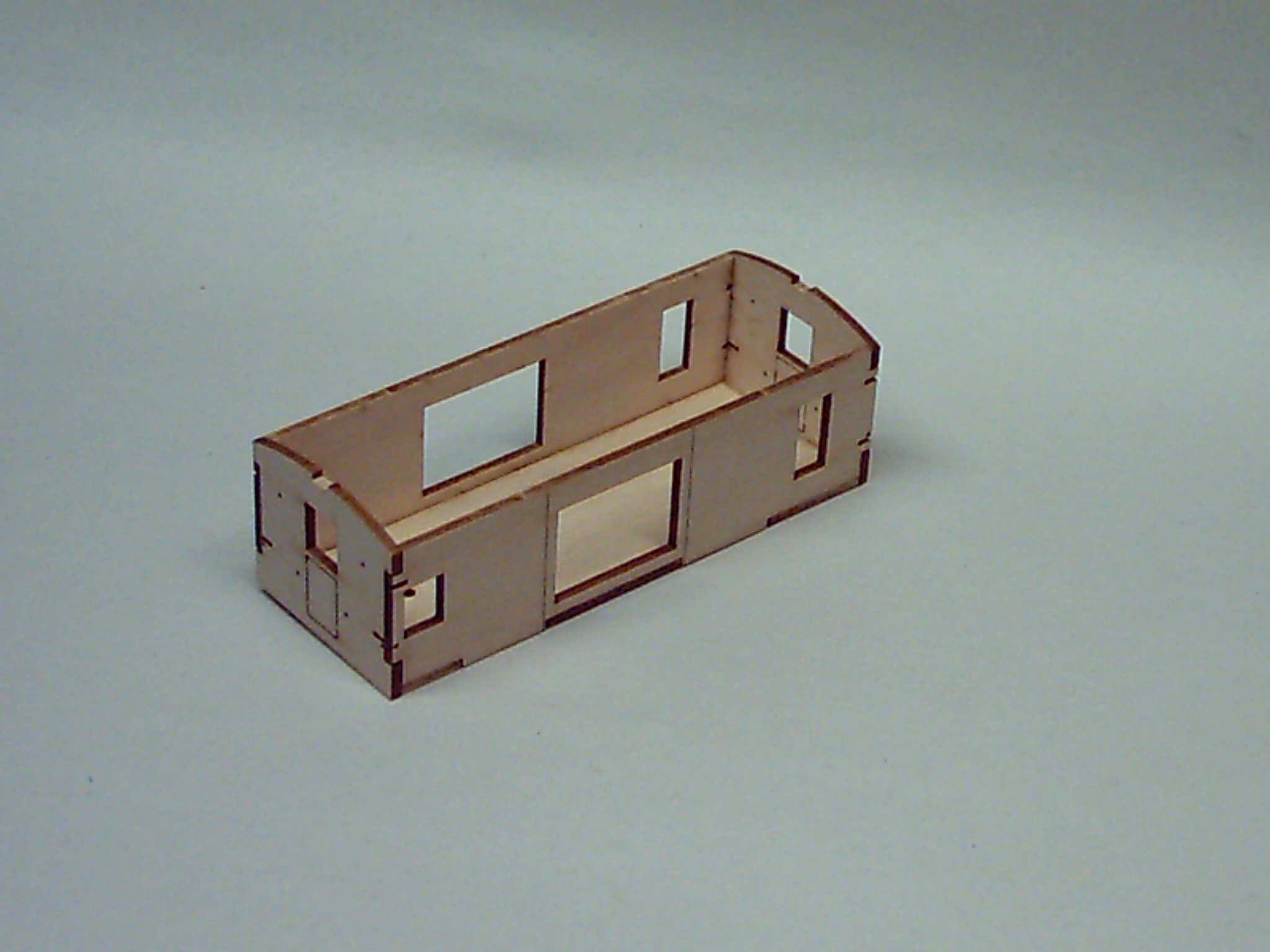 Step 2 from Above |
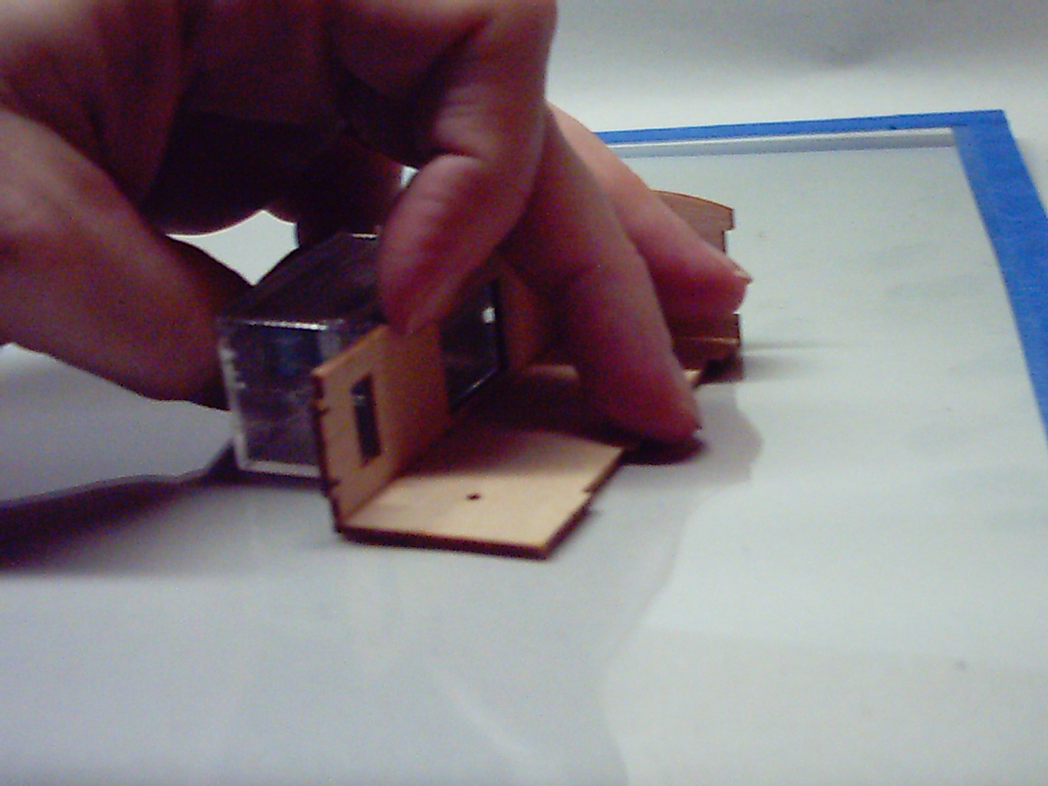
This
view shows the basic box with the end sheathing (9) added at the
completion of Step 3. Taking care to align the grab iron holes, I
verified that the end sheathing was flush with the vertical edges of
the sides and along the top edges of the subwalls on both ends. I
found that if I didn't press down, the tackiness of the Peel &
Stick sheathing would hold it in position and yet allow me to adjust
its position until I was satisfied. When I was, I pressed harder
on the end sheathing to fix it in place and then turned the body so
that end sheathing was against the glass surface where I could press
more firmly without any concern of damage. |
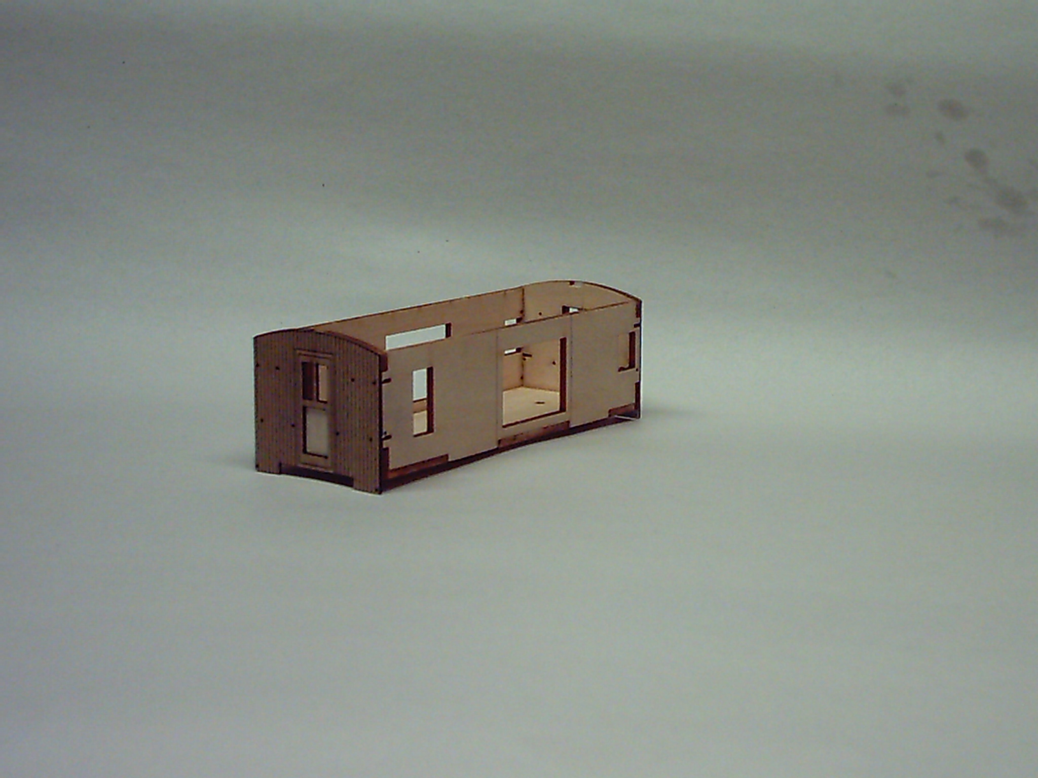 Step 3 |
This
view shows the basic box with the first piece of side sheathing being
added. My "Poor Man's angle block" really came in handy here
while trying to ensure that the sheathing was flush at the top edge and
set against the laser inscribed line adjacent to the bay
window. The one thing I should have paid more attention to was the
fit with the end sheathing. One of the pieces ended up being just
a bit shy of the end sheathing. I can feel it with my finger
though it's not too noticeable with my tired old eyes. So, it
will be interesting to see just how it looks once it's finished. |
 Step 4 Side Assembly |
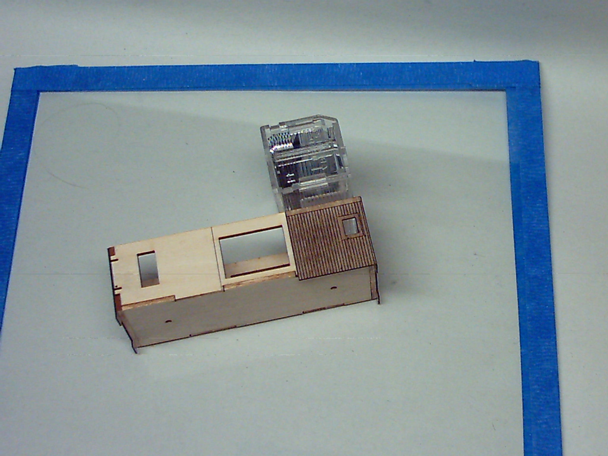
This
view shows the basic box with one of the filler (14) pieces being
added. Again, my "angle block" comes in very handy to ensure that
the filler is flush against the top edge of the box. |
 Step 5 Assembly |
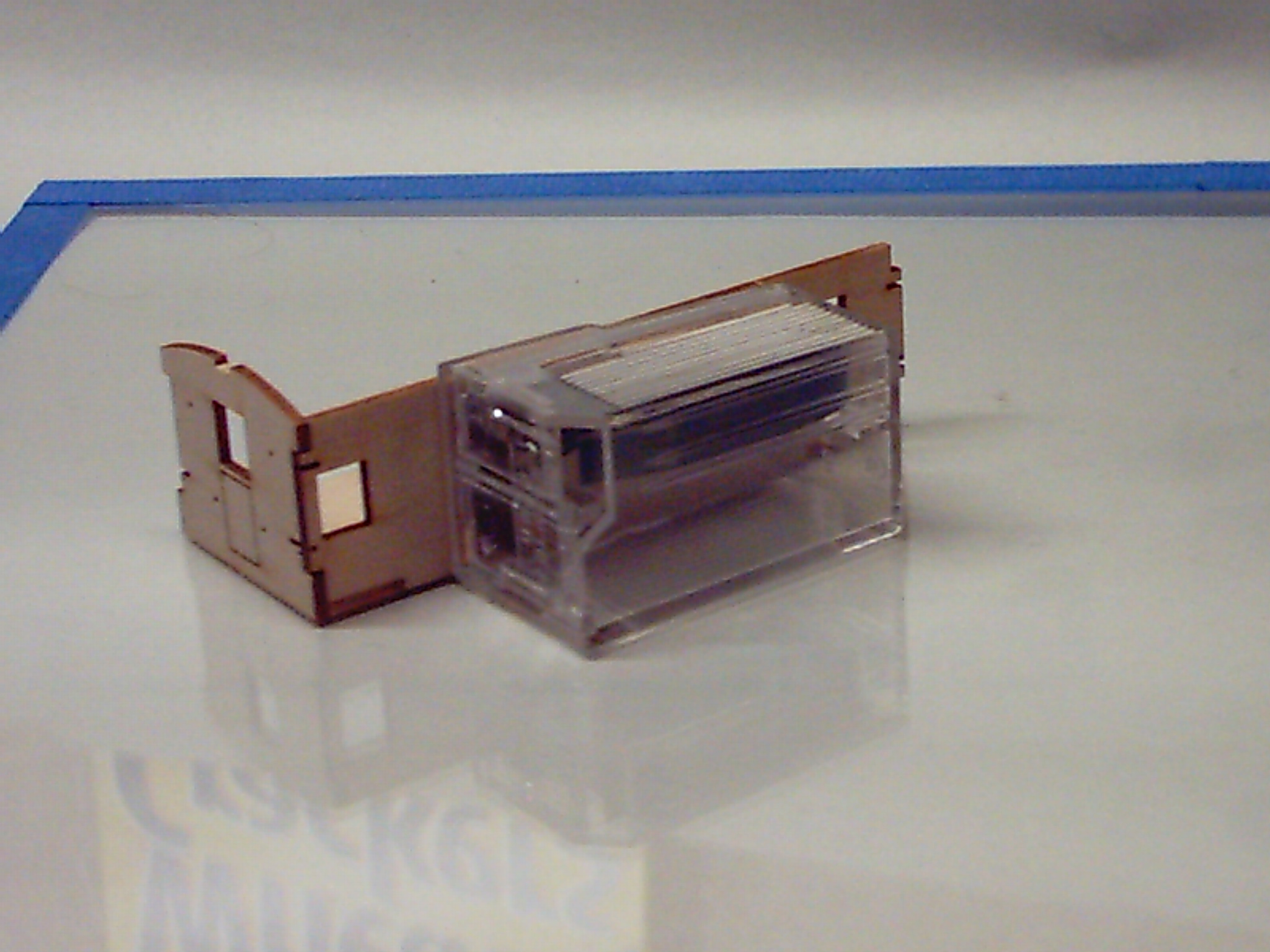
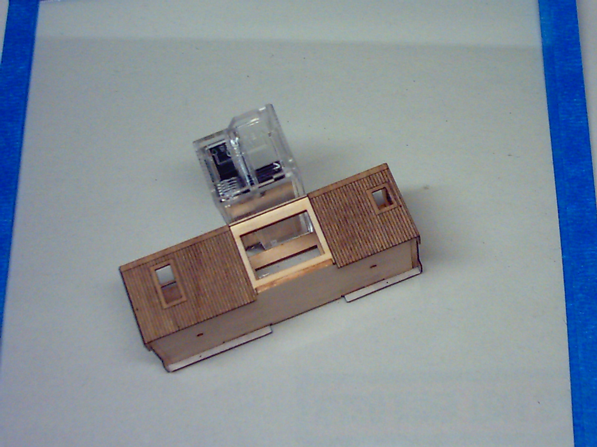
And,
this view shows the model at the completion of Step 5. A quick
test fit of the bay window casting at this point showed the fit of one
side to be very good and the other side to be slightly snug.
Undoubtedly, this is the side where the sheathing is just a bit
off. Anyway, it wasn't so bad that I had to do any surgery. |
 Step 5 |
More to come... |
|